Connect devices on the diagram
Lines between devices on a site diagram come from the Connections manager. You pick an interface on one device and an interface on another, and the diagram draws the link with both interface names at the ends. Connections are stored with the site, so they’re part of your inventory and not just a drawing.
Open the Connections manager
Section titled “Open the Connections manager”- Open the site’s diagram on the Topology tab (see Draw a site diagram).
- Make sure the Live Canvas tab is selected. Snapshots are read-only.
- Click 🔗 Connections in the toolbar.
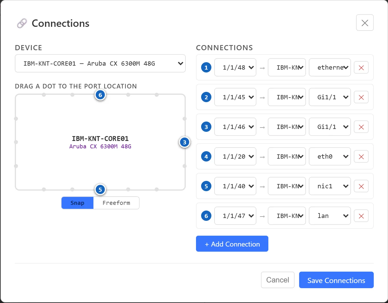
The manager shows one device at a time. Pick it from the DEVICE list at the top left. The list holds every device in the site, plus the Internet, Internal Networks and DMZ clouds, so you can link a device straight to a cloud.
Add a connection
Section titled “Add a connection”- In DEVICE, pick one end of the link, for example IBM-KNT-CORE01.
- Click + Add Connection.
- In the ADD CONNECTION row, pick this device’s interface from the first list.
- Pick the other device from target….
- Pick the other device’s interface from the last list.
- Click Add. The new link appears under CONNECTIONS with a number.
- Click Save Connections to apply your changes to the diagram.
The interface lists show the interfaces you’ve entered on each device, the names in its IP list such as port1, wan1 or 1/1/48. If an interface you need isn’t there, add it to the device in the device editor first.
Edit or remove a connection
Section titled “Edit or remove a connection”Each row under CONNECTIONS reads as this interface → other device other interface.
- To change an end, pick a different interface or device in that row.
- To remove a link, click ✕ at the end of its row.
- Click Save Connections when you’re done.
Automatic links to the clouds
Section titled “Automatic links to the clouds”Interfaces with the WAN, LAN or DMZ role get a link to their cloud automatically, for example a firewall’s wan1 to Internet. These show in the list as gray rows marked ⚙. They aren’t stored as connections until you change them: pick a different target or interface, or drag the row’s dot, and the row becomes an ordinary connection that you can edit or remove.
Choose where a line attaches
Section titled “Choose where a line attaches”The box on the left, under DRAG A DOT TO THE PORT LOCATION, stands for the selected device. Each numbered dot is one of its connections, with the same number as its row in the list.
- Drag a dot to the side of the box where that port should be. A dot placed on the bottom edge makes the line leave from the bottom of the device on the diagram.
- Use the toggle below the box to choose how dots move:
- Snap moves a dot to the nearest preset point: five along the top and bottom, three on each side. The same points exist on every device, so links line up neatly at both ends.
- Freeform lets a dot sit anywhere on the outline.
- Click Save Connections.
Attach points you set here are kept when you use ⟳ Tidy up on the diagram.
HA pairs
Section titled “HA pairs”For a device marked as an HA pair, an HA UNIT list appears under the box. Choose Primary or Secondary to manage that unit’s connections. Each unit has its own links, so you can wire the secondary firewall to a second core switch port, for example.
Label the lines
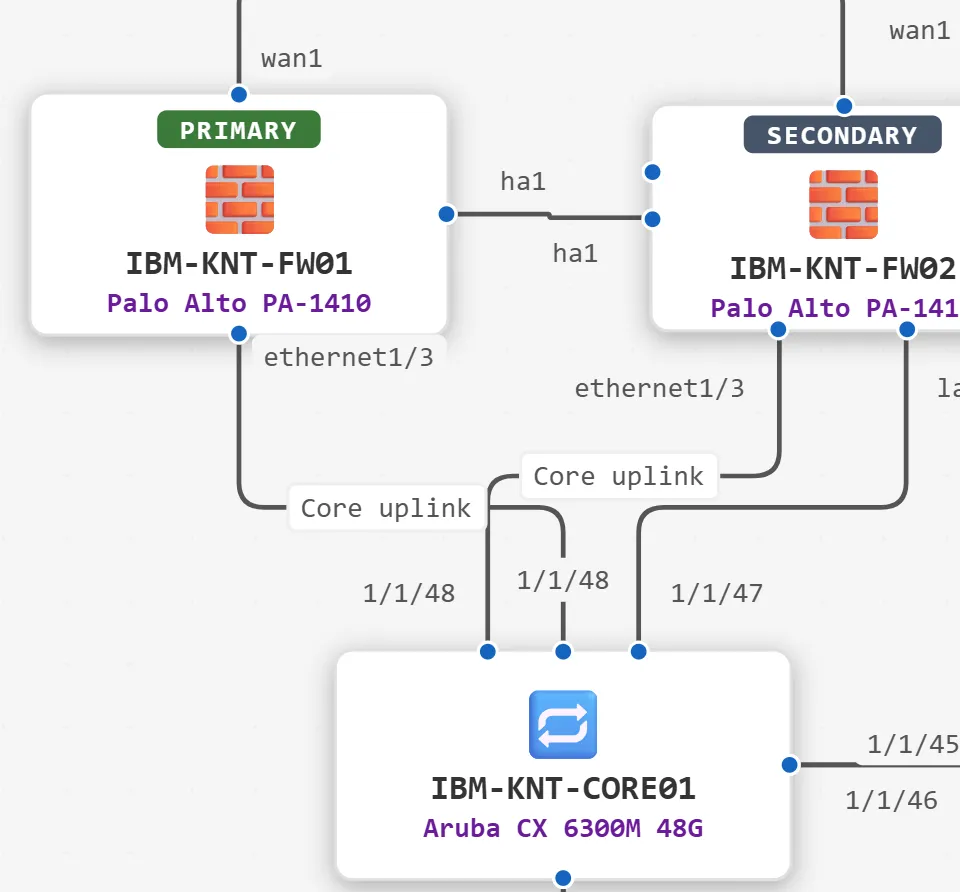
Section titled “Label the lines”Each end of a line carries the interface name from the connection, so a link from ethernet1/3 on the firewall to 1/1/48 on the core switch shows both names next to the devices.
You can also put a label in the middle of a line, such as Core uplink, PoE or a circuit ID:
- On the Live Canvas, double-click the line.
- Type the label.
- Press Enter to save it, or Esc to cancel.
To change a label, double-click it. To remove it, double-click it, delete the text and press Enter.
To move an interface name at the end of a line, drag it. Double-click it to put it back in its automatic spot.